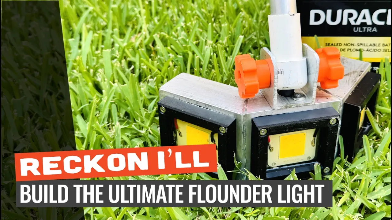
DIY: Make a No-Weld Flounder Light That'll Light Up the Ocean
I only recommend products I believe in and use myself. If you purchase something using a link to an item on a post, I may earn a small commission at no additional cost to you. Read More
If you built my original flounder gigging light, you know it put out more than enough light to light up the ocean. But after years of testing, walking the the shallow salt flats for hours, I think I can make some updates.
My main goals:
Build it with basic tools i.e. no mig spool guns, etc
Lower the weight
Increase the ridgidity
Build a comfortable handle
This build swaps out the flexible PVC main shaft for rigid 6061 aluminum round tube and drops down to easier to handle (and lighter) 16-2 marine gauge wire.
I'm still reusing the original 1-inch Type LL PVC conduit body at the top of the pole, but adapting it to the new aluminum shaft with a much slicker bushing trick.
To make it even easier to carry, I designed a custom handle and wrist cuff setup based on a metal detector layout, allowing your entire arm to support the weight of the light while keeping your hand free to steady your gig.
Part I: Fabricating the Housing
Step 1: Prep and Cut the Aluminum Housing
Cut three 3.5-inch pieces of your 3-inch x 1.5-inch aluminum rectangle tube to build the light head. Scribe 22.5-degree miters on the connecting ends to allow the the three pieces to be joined together and shine in different directions. Keep the outside edges of the two side pieces completely square.
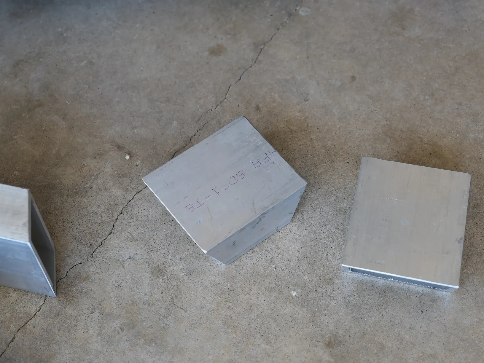
Be sure to bevel all the edges to allow for brazing later.
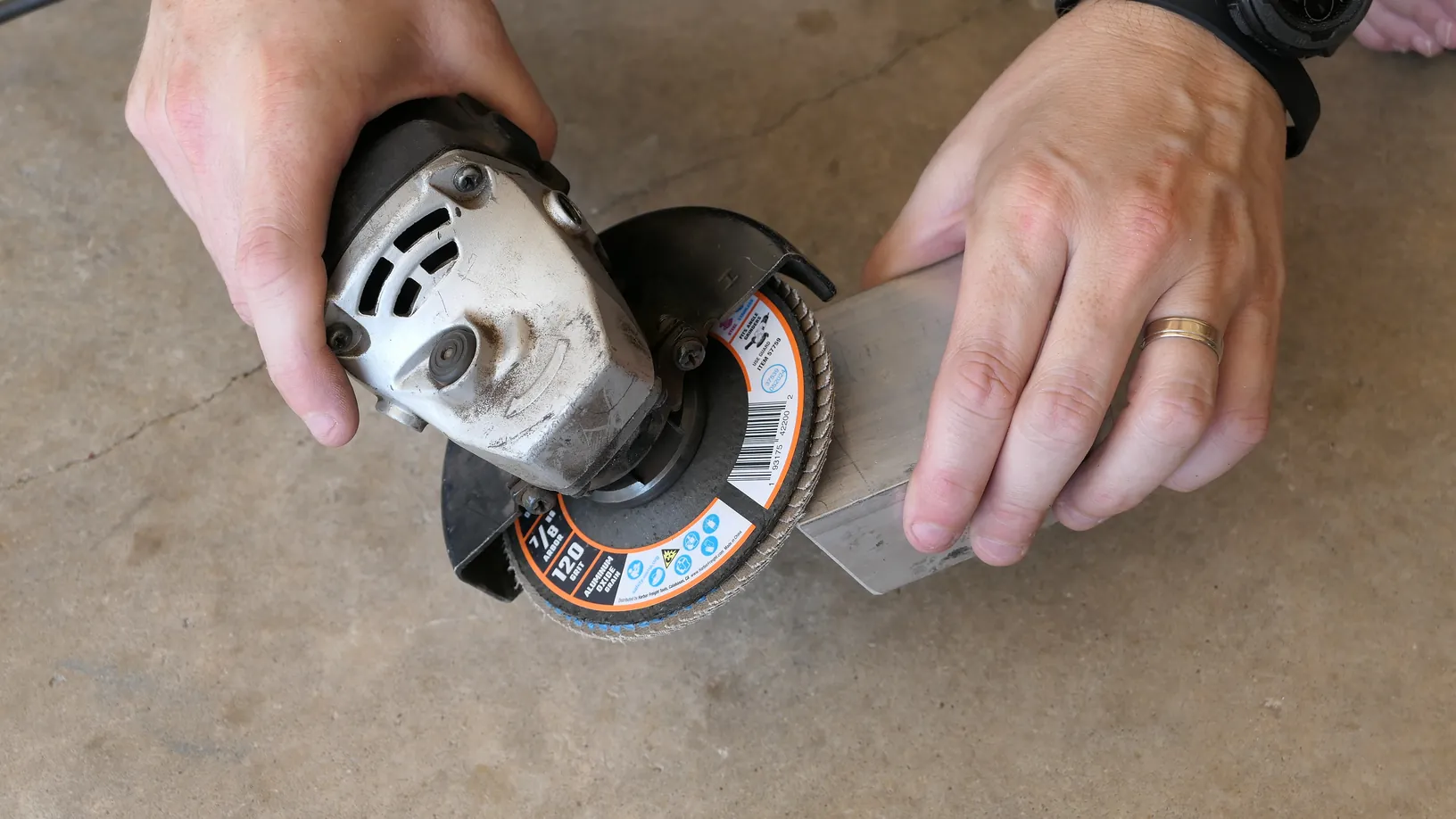
Step 2: Fabricate the Epoxy Surround Frames
You need a raised border on each face of the aluminum housing to pool and hold the waterproofing epoxy over your LED chips. Choose one of two options to make these frames:
Option A (3D Printing): Print custom-designed frames out of ABS filament. This gives you a rigid, heat-resistant seal that fits the contours of your housing.
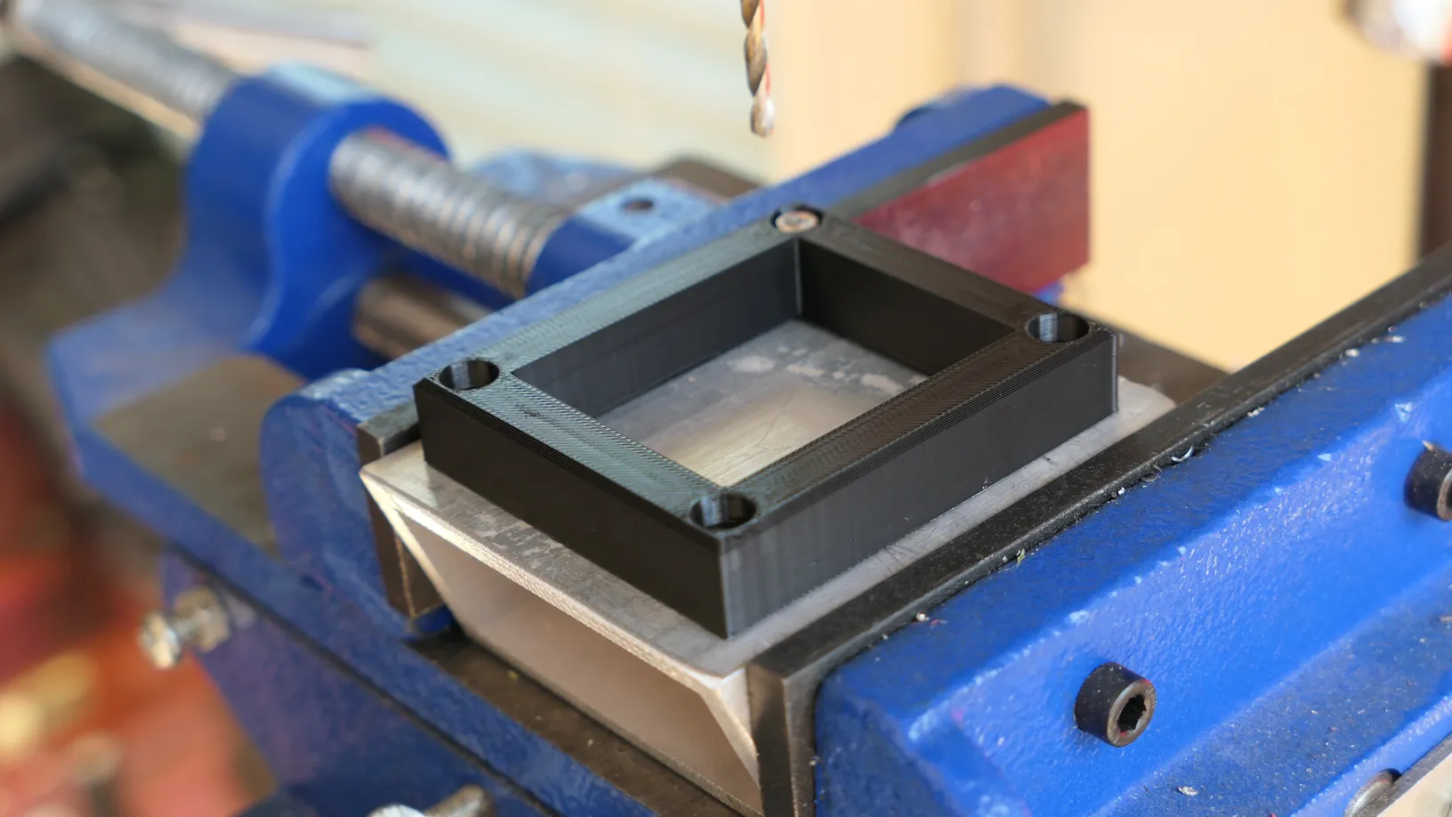
Option B (The Cutting Board Hack): Grab a cheap plastic cutting board or any sheet of HDPE you have scrounged up. Scribe matching square borders onto the plastic and use a jigsaw to cut them out.
Step 3: Drill and Tap Frame Mounting Holes
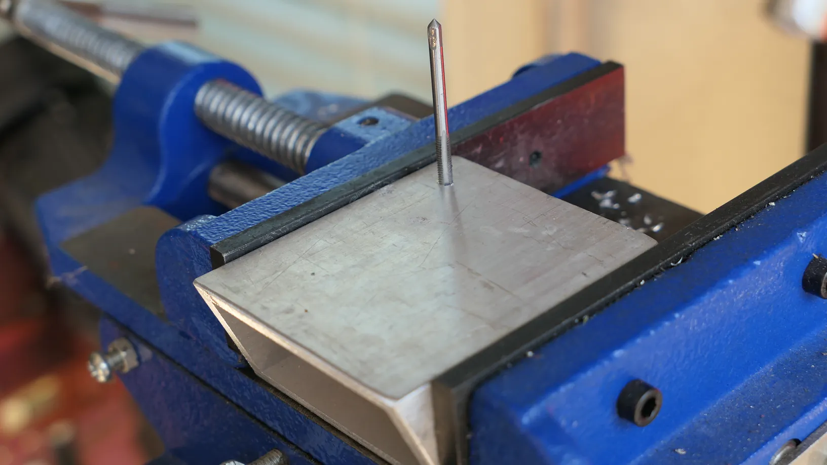
Position your newly fabricated epoxy surround frames onto their respective aluminum tube sections. Drill and tap mounting holes directly into the aluminum face us at M4 x .7 tap. I use a traditional tap for this, but Harbor Freight also sells an all-in-one drill bit and tap in this size.
Take your time drilling one hole at a time to ensure a good fit where all holes are accessible. Remove the plastic or 3D-printed frames after tapping and set them aside.
Step 4: Drill the Wiring Access Hole
Drill a 1-inch wiring access hole into the back wall of the middle housing section. Doing this on the drill press while the middle piece is still separate and easy to clamp makes it infinitely easier to get a clean, centered cut.

Step 5: Fabricate and Drill the Hinge Bracket
Cut a 1.5-inch section of 1.5 x 2-inch aluminum square tube. Drill a 1/4-inch horizontal hole through the bracket walls for the hinge bolt.

Drill two 1/4" holes through the bracket (one at a time) into the center housing and tap the center housing with a 1/4-20 tap. These will be used to secure the bracket to the light housing.
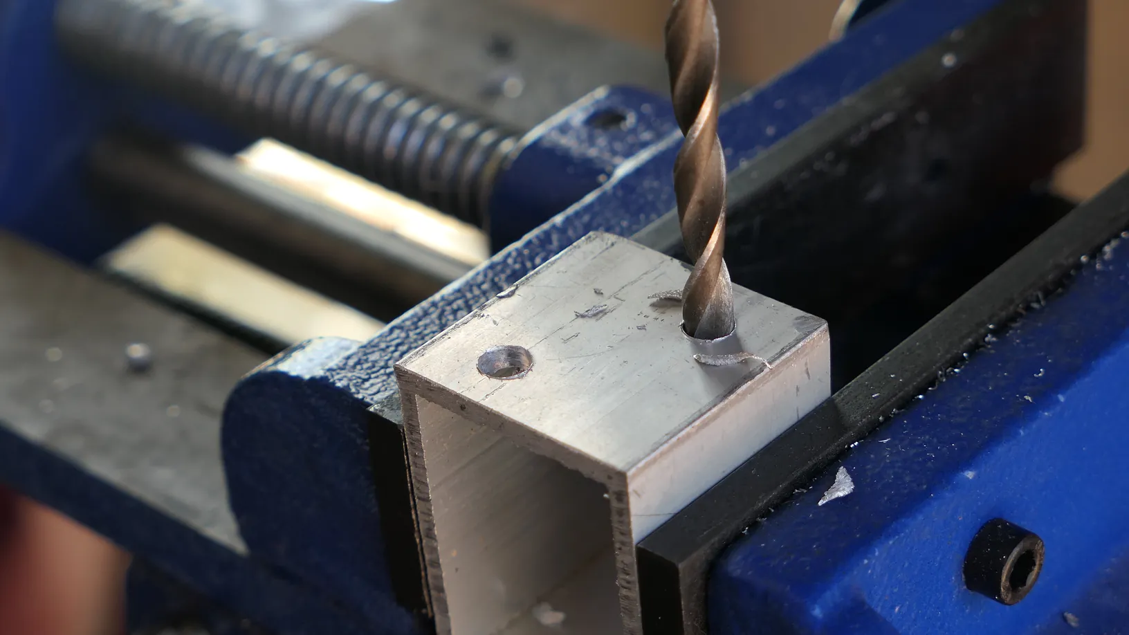
Drill a 5/8-inch hole through the bracket between the 1/4" holes for the marine wire to pass through into the pole. Drill the same size hole through the center housing. It easiest if you first drill a 1/4" hole through both while attached and then widen.
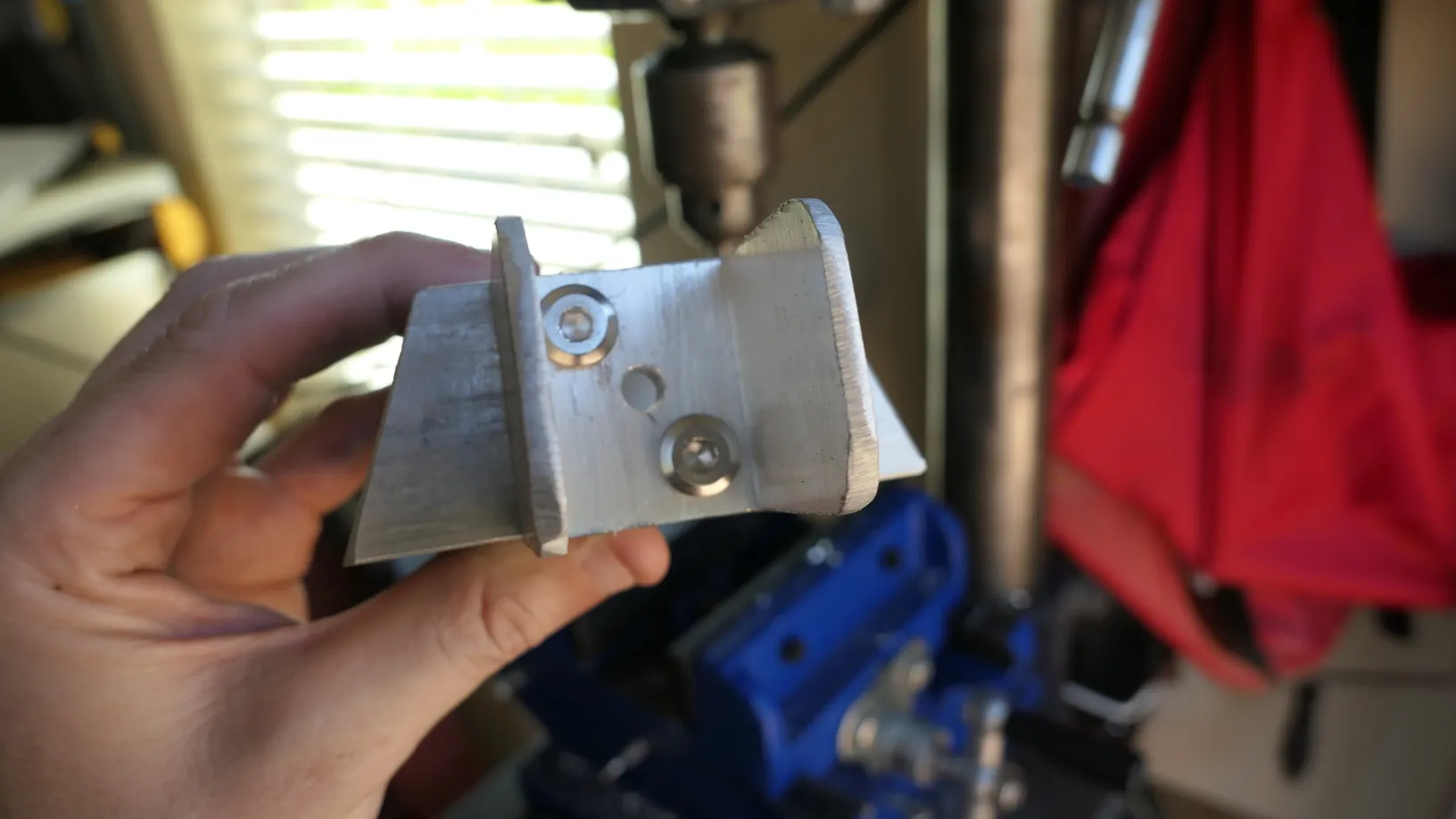
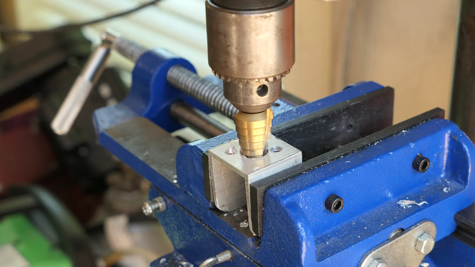
Remove one wall to create a rigid U-shaped bracket.
Step 6: Round the Edges of the Bracket
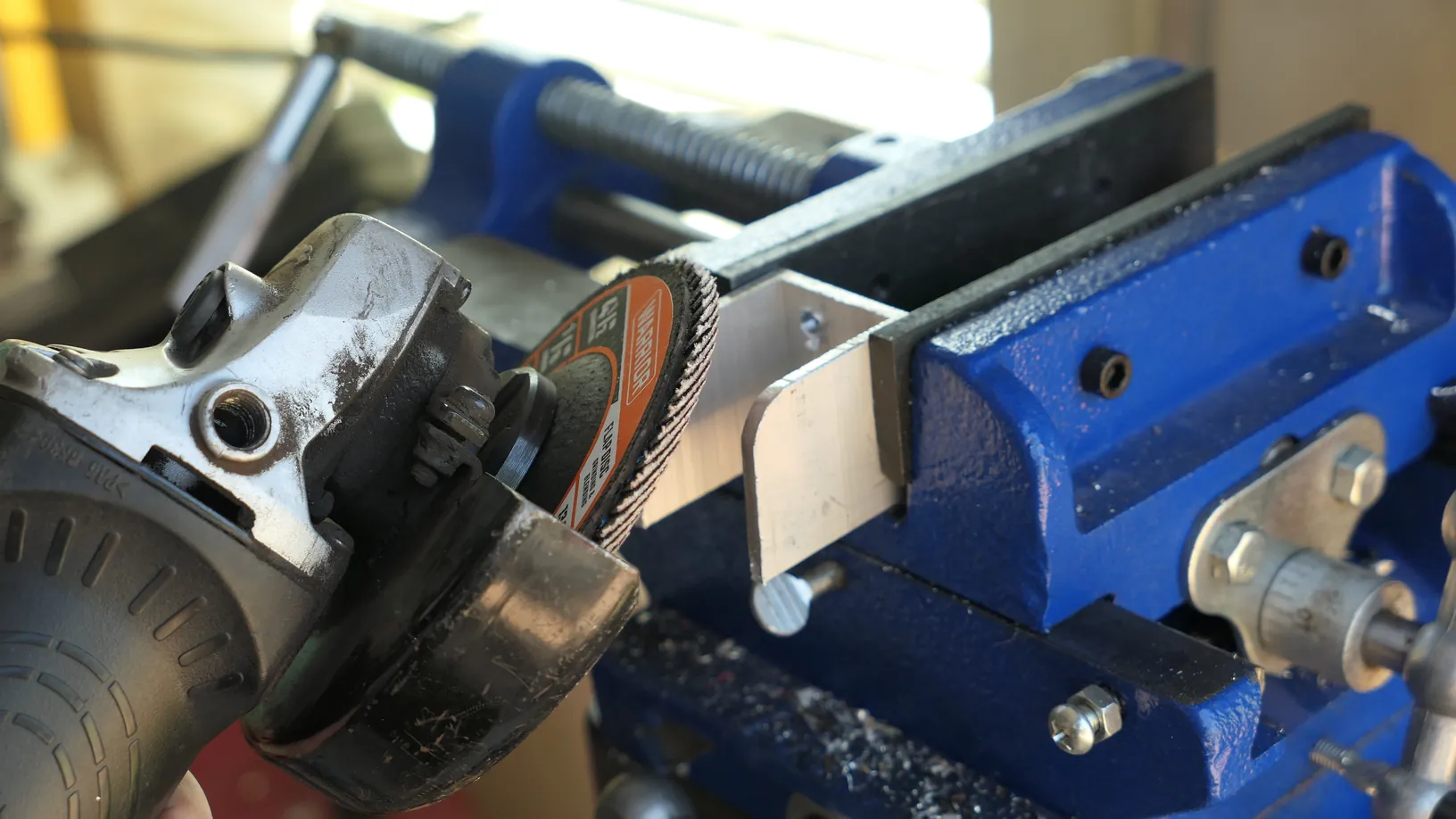
Using an angle grinder, round off the sharp edges of the bracket.
Step 7: Braze the Housing Together
Clamp the three mitered rectangle tubes together to form your final curved shape.
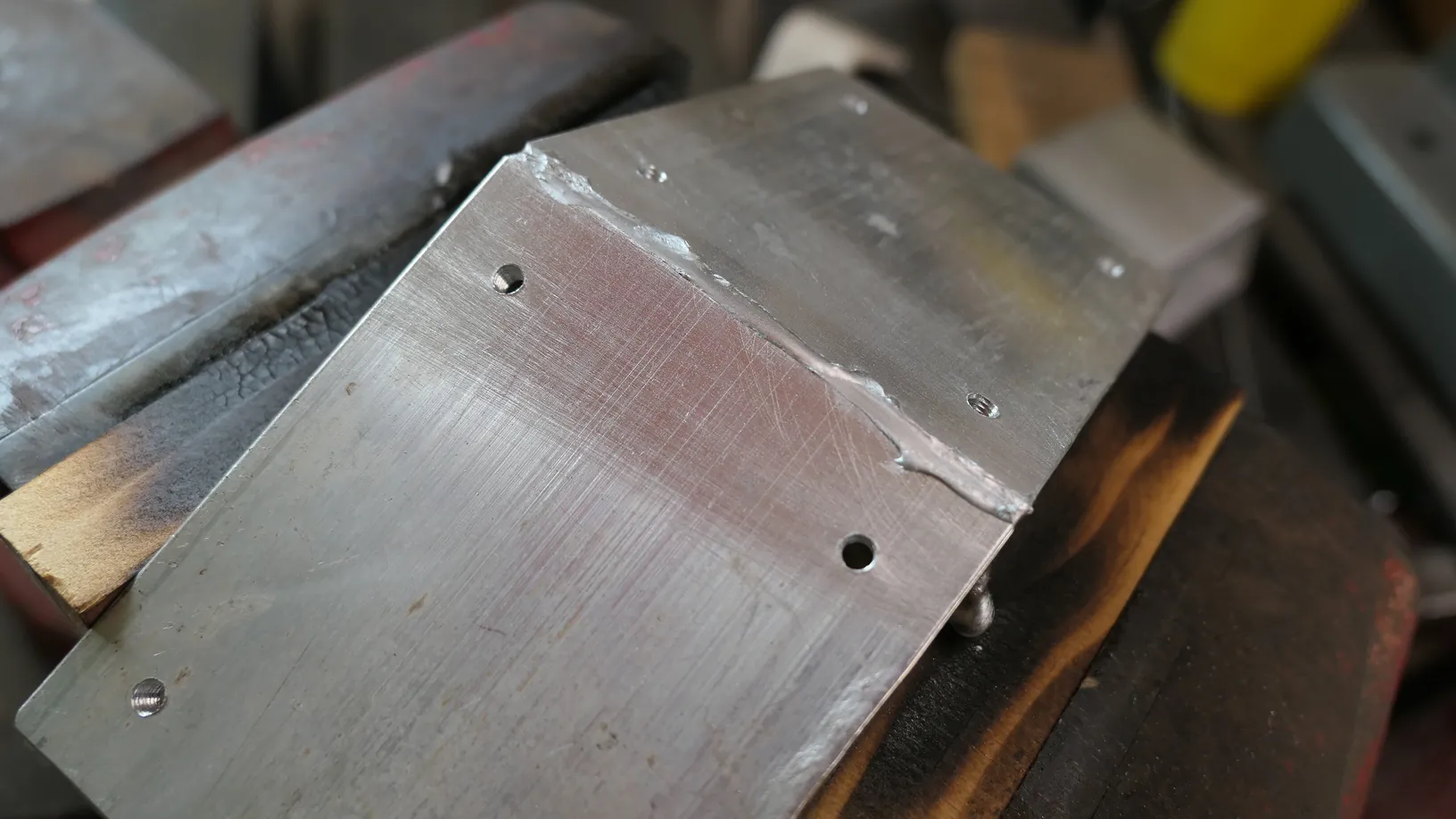
Heat the aluminum joints with a MAP gas torch and apply aluminum brazing rods to seal the seams.
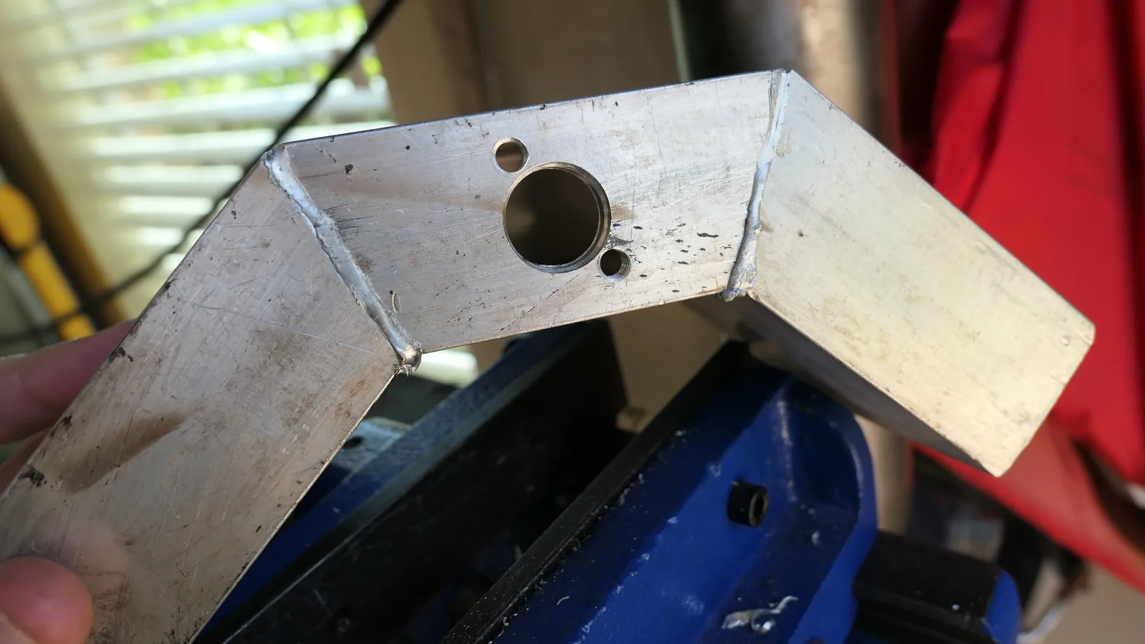
Let the welded metal cool completely to room temperature before handling.
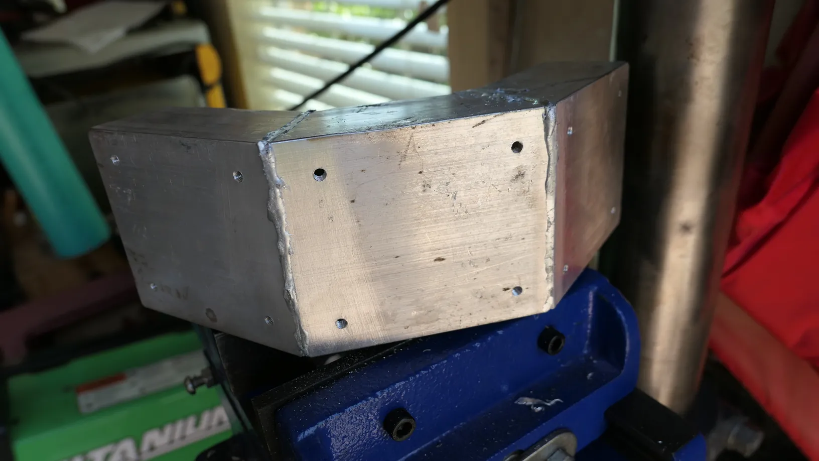
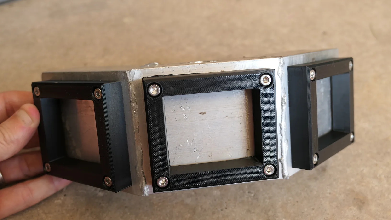
Step 7: Reattach the Epoxy Surround Frames
Align your plastic or 3D-printed ABS surround frames over the cooled, brazed aluminum housing. Fasten them back in place by driving M4 x 20mm stainless steel screws with a little bit of red loctite directly into the pre-tapped holes you made in Step 3.
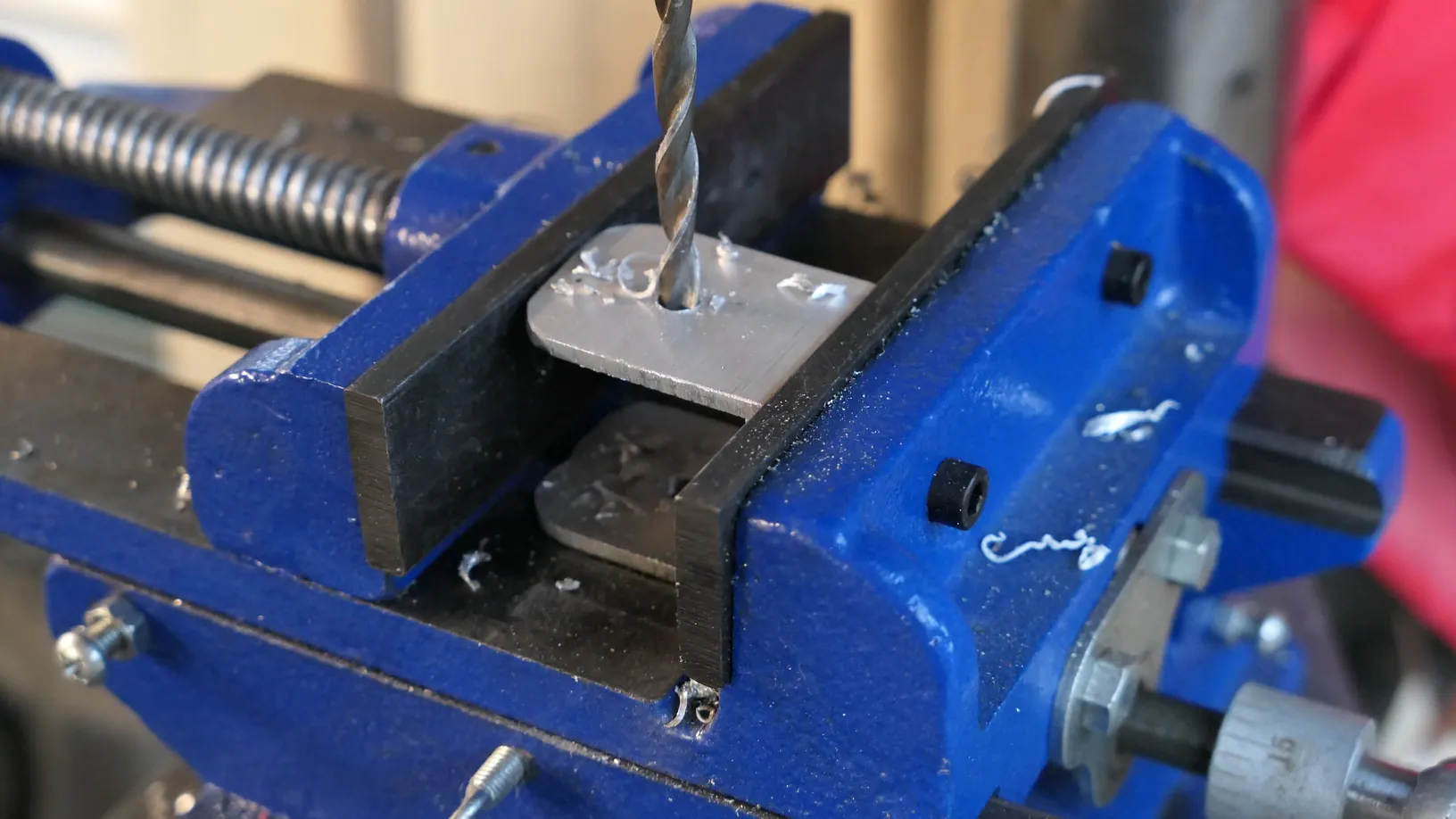
Step 8: Drill the Hinge
Drill a 1/4-inch through-hole off center towards the rounded top of the aluminum hinge.
Step 9: Drill Wiring Holes
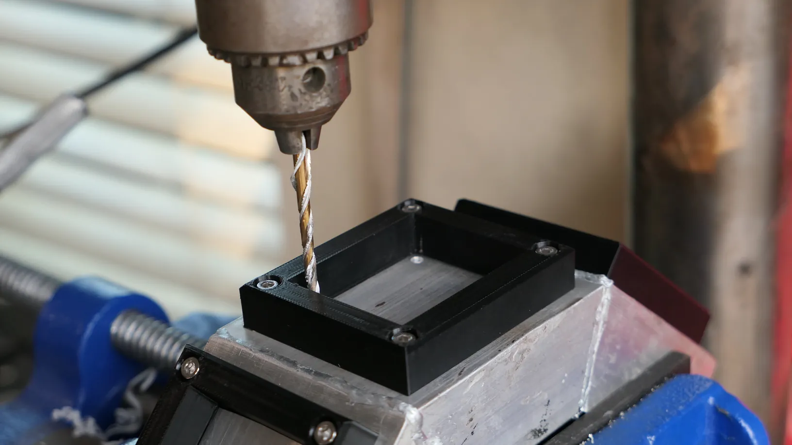
Drill a 1/8-inch hole in the top right and left corners of each surround frame (these will be used for wiring in the future).
Step 10: Attach the Top Hinge
Using 3/4" 1/4-20 bolts, attach the hinge to the top of the middle housing.

Materials Needed
(May Contain Links that Earn Commission)
•
3″ x 1.5″ Aluminum Rectangle Tube (3 pieces at 3.5" with 22.5deg bevels)•
2" x 1.5" Aluminum Rectangle Tube (for hinge)Tools Needed
(May Contain Links that Earn Commission)
•
1" Hole Saw (or just use the step bits)Related 3D Prints
Part II: Building the Pole
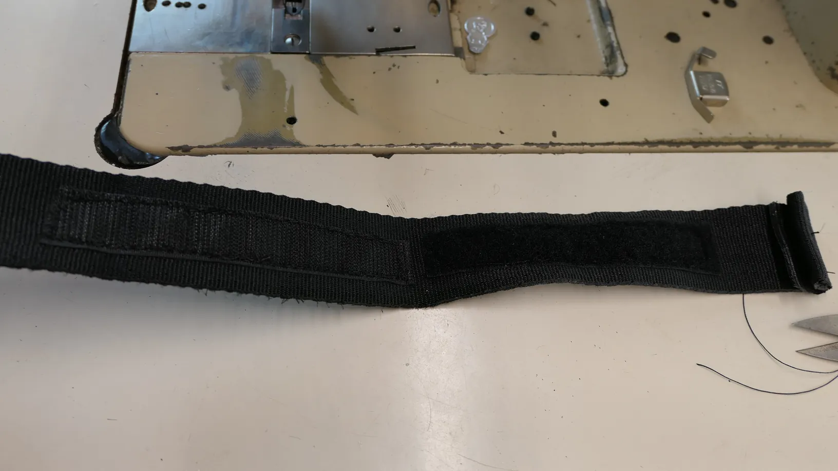
Step 1: Sew the Cuff Strap
Using 1.5" strapping and hook & loop, sew a strap to add your 3D printed cuff.
Step 2: Slide on the Cuff & Handle
Before you add any sleeves to the aluminum pole, slide your cuff and handle assemblies onto the raw 7/8-inch aluminum tube. Set these up using one of two methods:
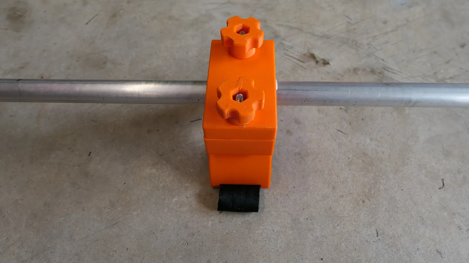
Option A (The 3D-Printed Setup): 3D print (using the linked files) the custom handle and wrist cuff in PETG or another heat-resistant filament and the friction sleeves in TPU. Secure the handle and wrist cuff to the pole using custom 3D-printed knobs loaded with 1/4-20 nyloc nuts and a 1/4-20 x 2.5-inch stainless bolt driven through the handle.

Option B (The Hardware Store Setup): Order an off-the-shelf metal detector cuff….7/8" is standard.
For the handle, use a 1/2-inch x 1/2-inch PVC Compression Tee Fitting with a 1/2-inch FIP Branch. Drill out the internal pipe stop inside the tee so it can slide freely over the 7/8-inch aluminum pole.
Screw a 1/2-inch threaded-to-slip adapter into the tee's female branch, and glue a 6-inch section of 3/4-inch PVC into the slip port to serve as your hand grip.
Step 2: Sleeve the Top (Enclosure) End of the Pole
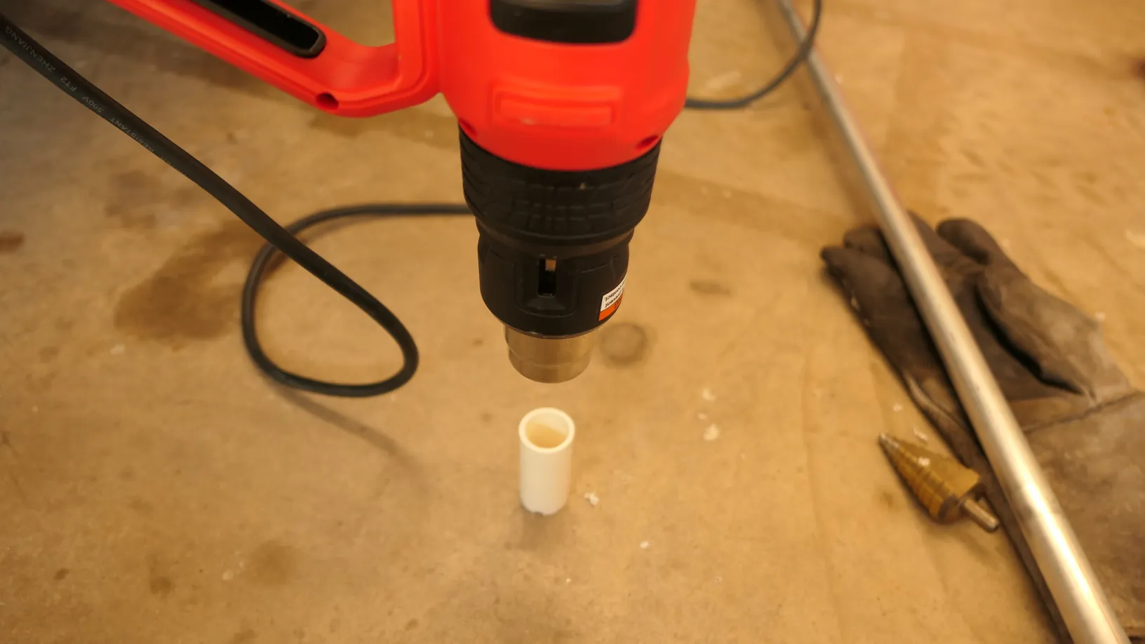
Cut a 3.5-inch sleeve of standard 3/4-inch PVC pipe. Hand-turn a step bit inside the rim of the PVC sleeve to slightly chamfer the inside edge.
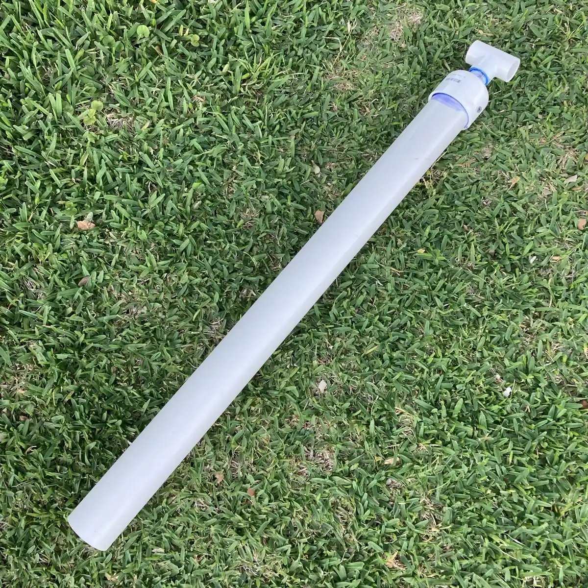
Use a heat gun to gently warm and soften the PVC, then drive the top end of your 7/8-inch aluminum pole into the sleeve until it is completely flush.
This sleeve increases the diameter of the aluminum pole just enough so you can glue it cleanly into the 1-inch to 3/4-inch PVC bushing on your LL conduit housing.

Step 3: Sleeve and Cap the Hinge End of the Pole
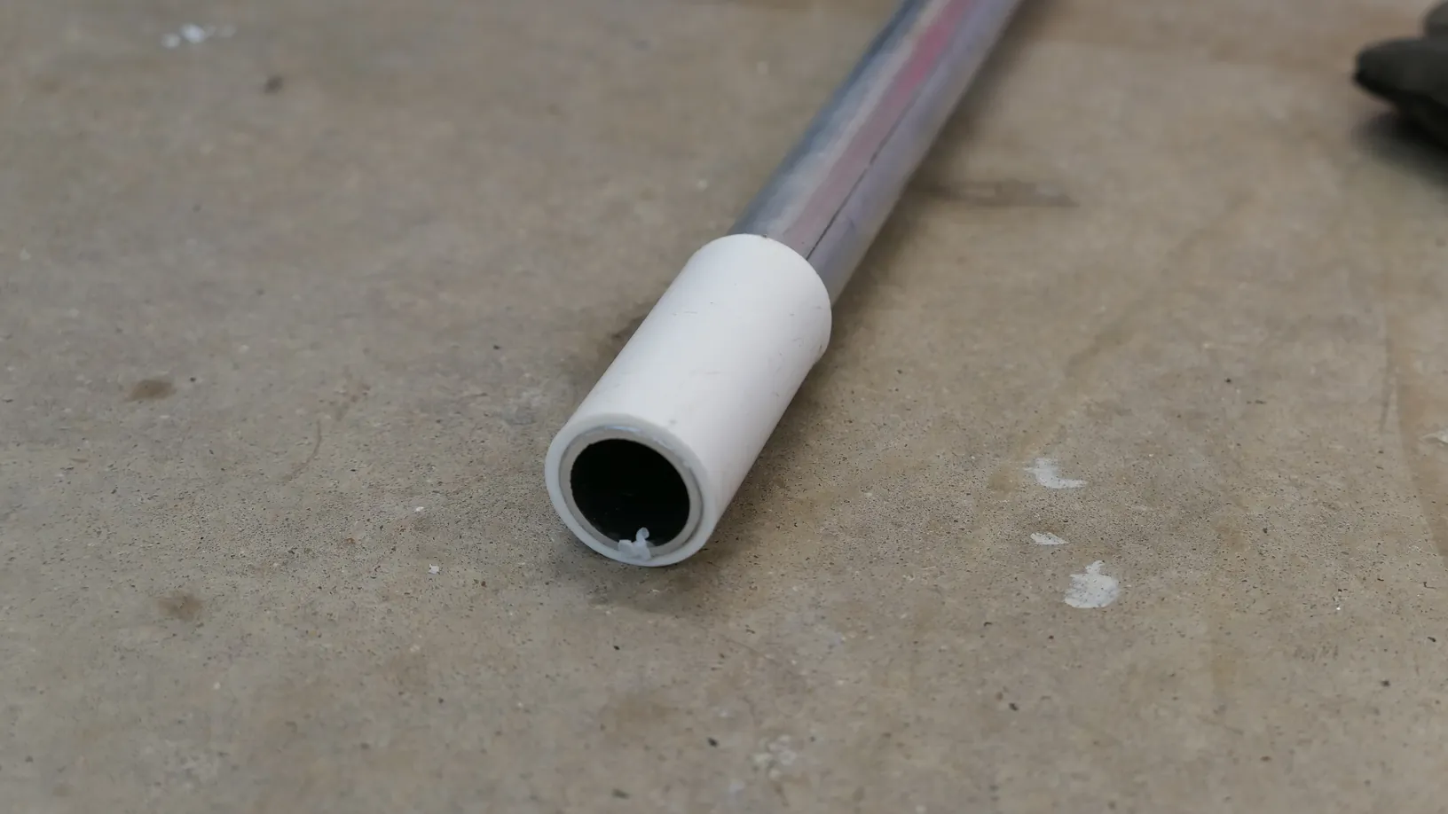
Cut a 2.5-inch sleeve of 3/4-inch PVC pipe. Chamfer the inside of this sleeve using your step bit, heat it with the heat gun, and drive the bottom end of the aluminum pole flush inside it.
Step 3: Drill a Hole in End Cap
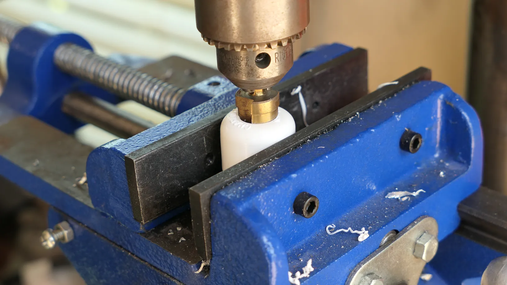
Next, drill a 5/8-inch hole using a step bit directly into the center of a standard 3/4-inch PVC cap.
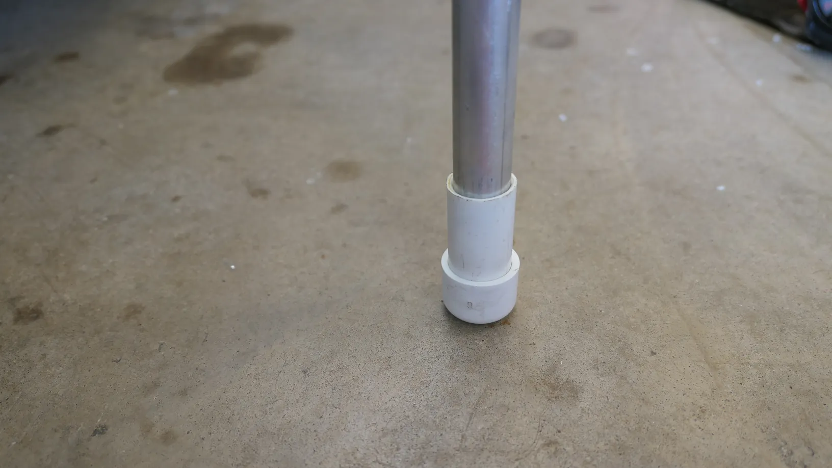
Drive this cap onto the 2.5-inch sleeve to seal the edge while leaving an exit port for your wiring.
Step 4: Drill Through the Capped Aluminum Pipe
Drill a 1/4-inch through-hole straight through the PVC cap, sleeve, and internal aluminum pole.

Step 6: Test Fit Attaching the Housing
Attach the aluminum U-bracket to the housing using 3/4" 1/4-20 bolts.
Option A (The 3D-Printed Setup): Secure the pole to the bracket using a 2.5" 1/4-20 bolt and a 1/4-20 nyloc nut pressed into 3D printed start enclosures.
Option B: Secure the pole to the bracket using a 2" 1/4-20 bolt and terminate it with a 1/4-20 butterfly nut (wing nut).
Loosening and tightening this hinge allows you to adjust the light head without a tool to get the proper angle in the water.

Materials Needed
(May Contain Links that Earn Commission)
•
B0CMQJG7YFPart III: Wiring the Light
Step 1: Route 16ga Marine Wire to Each COB
Without the pole attached, pass a ~7" length of 16ga marine wire to each COB.

Step 2: Mount and Solder the LED Chips
Apply a thin, even layer of thermal paste to the back of each 50W LED chip.
Solder the positive and negative wire to the COB .
(Tip: We run three independent lines because these high-draw 50W COB chips pull around 4 amps each at 12V; separating the circuits prevents voltage drop and keeps your wiring cool.)

Step 3: Waterproof the Housing
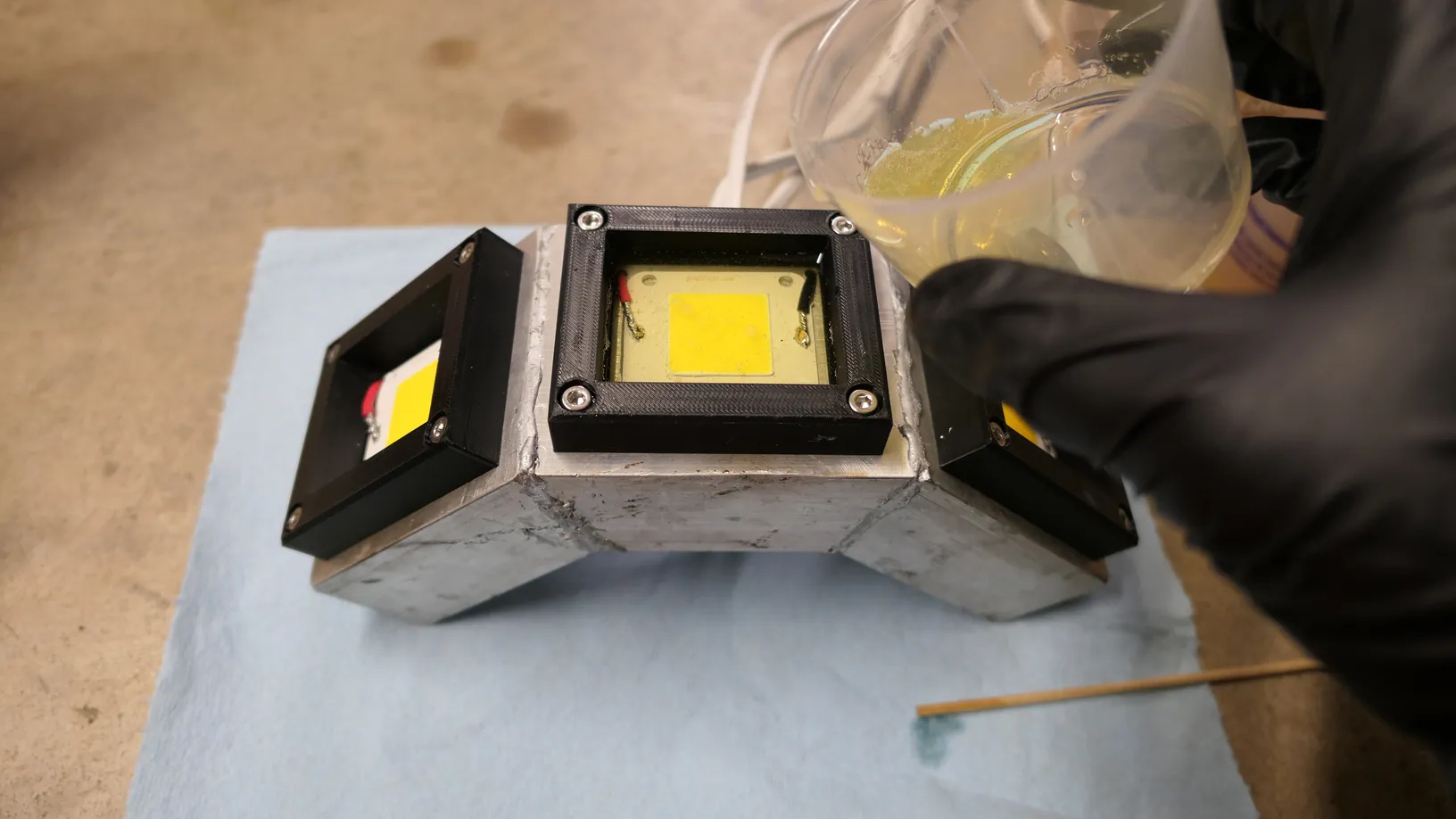
Mix your Varathane Super Glaze epoxy exactly as directed on the packaging. Because your light head is curved, you must pour one chamber at a time. Set the light head flat on your bench, pour the clear epoxy over the mounted LED chip until it completely covers the wires, and sweep a heat gun quickly over the surface to release any trapped air bubbles. Allow each chamber to cure fully before angling the head to pour the next one. Some will leak through the holes if you don't pre-epoxy the surrounds.
Step 4: Install Conduit Reducer Bushing
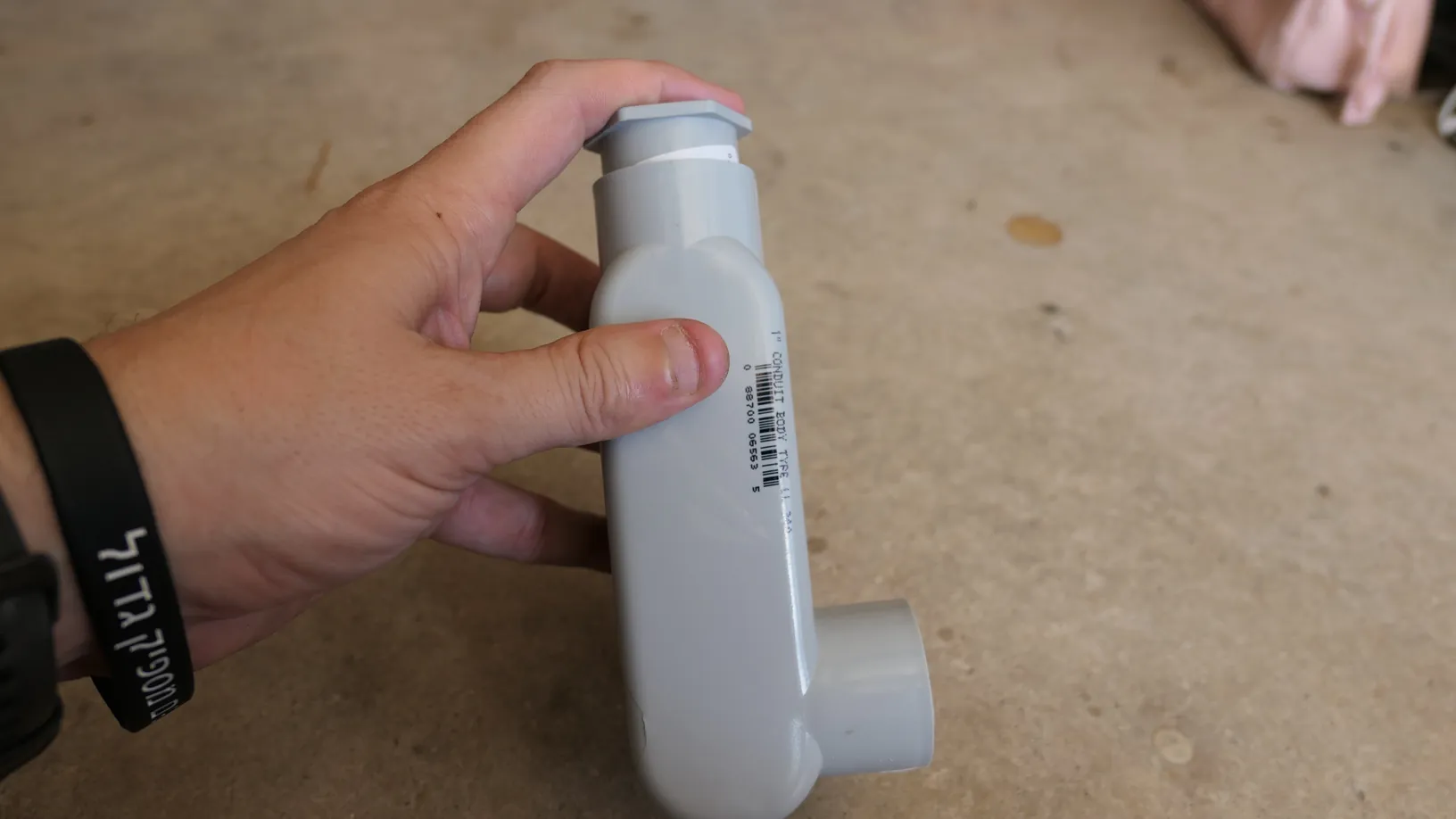
Press fit a 1" to 3/4" reducer bushing into the end of the LL conduit enclosure.
Step 5: Install Rocker Switches
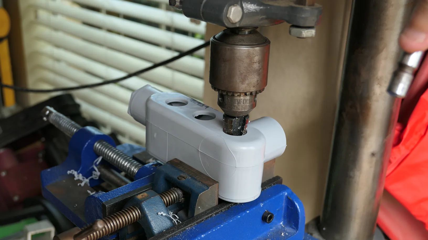
Drill three 20mm holes in a neat line through the backside of your LL enclosure and press-fit your toggle switches. You can use a little super glue or marine epoxy to hold them in place if they want to push out.

Step 6: Protect Wire Passthrough
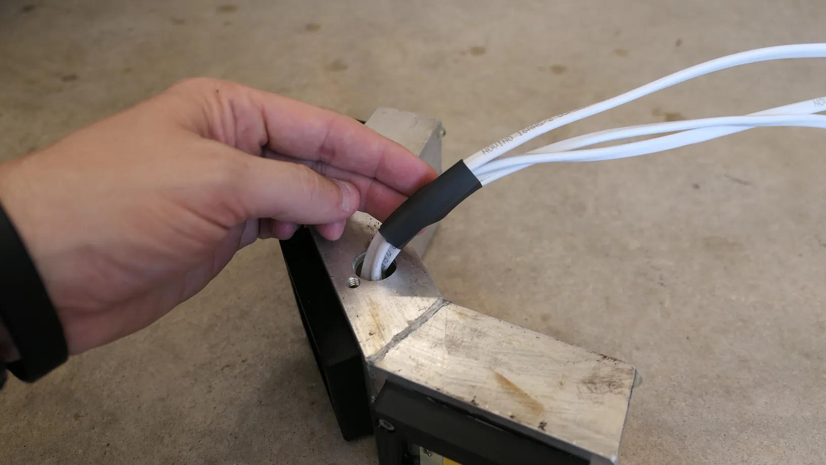
Install a 1/2" piece of heatshrink where the 16ga wires pass through the housing for extra protection.
Step 7: Install the Aluminum Pole
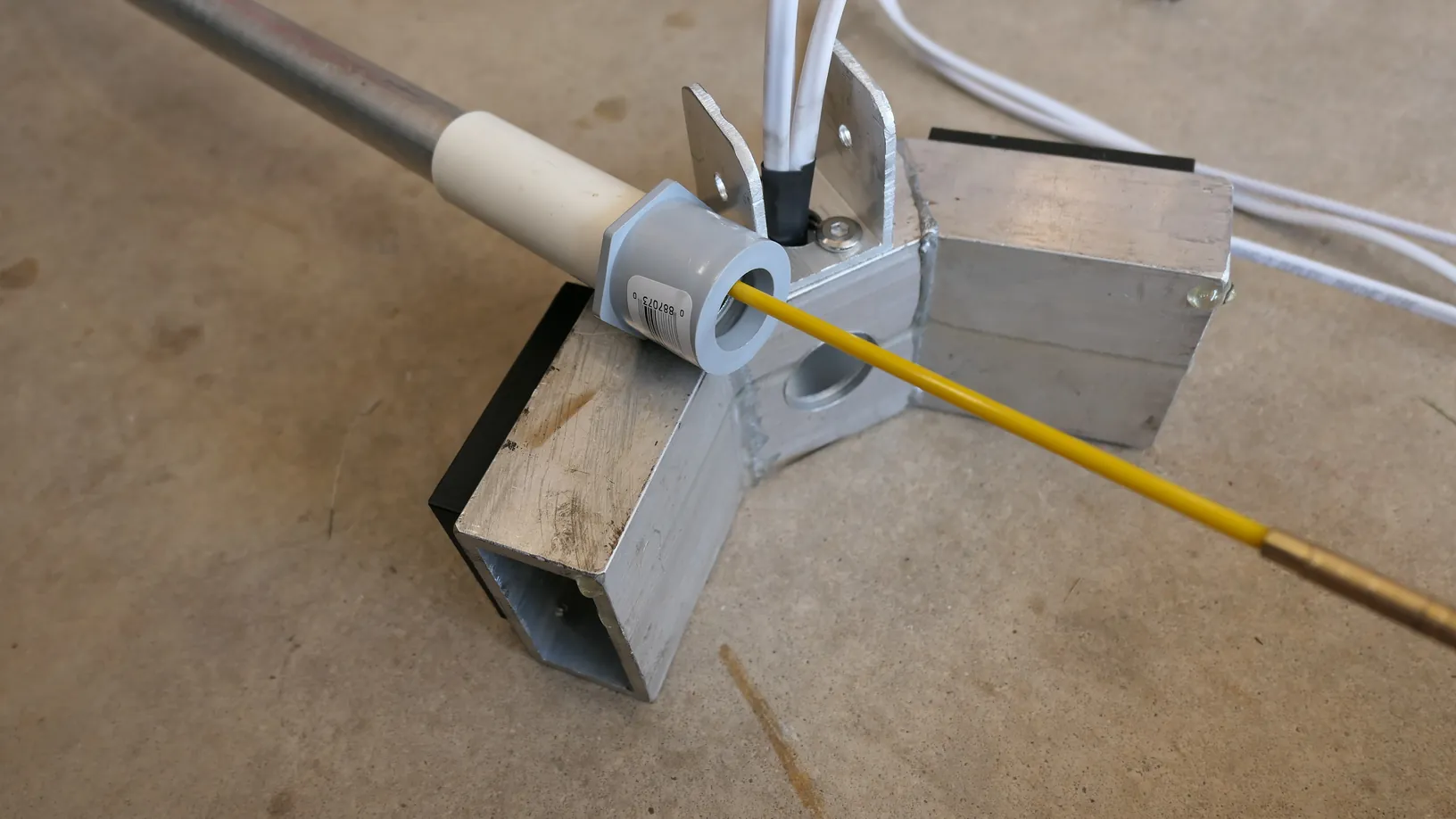
Using a fishtape/rod, pull the three lengths of wire through the aluminum pole. Its easier if you pull with the LL conduit body removed.. Fasten the pole to the hinge using either 3D printed knobs or a bolt and wingnut.
Step 8: Wire the Rocker Indicator Lights
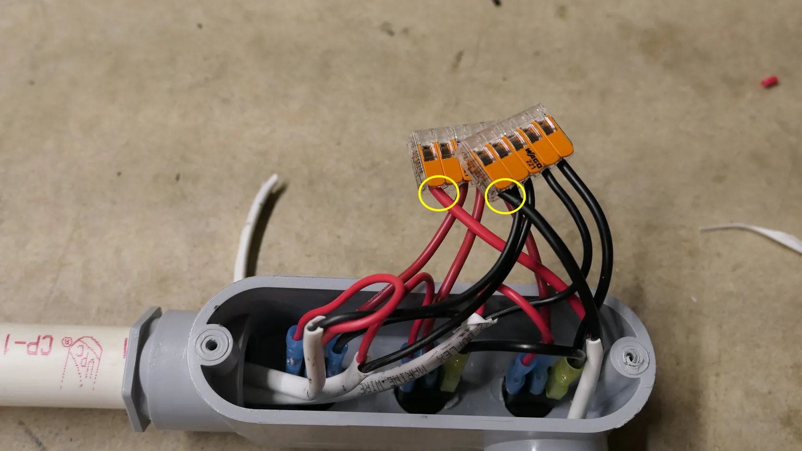
Chain the gold terminal using female spade terminals across all three switches and connect to a 5 port Wago.
Step 9: Connect Positive-load side of the circuit
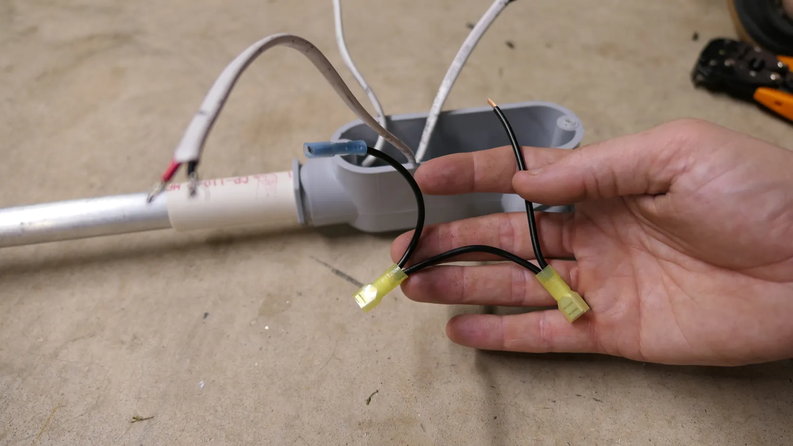
Using a 5-port Wago and 16ga wire (or greater), create a female spade jumper for each switch and connect to the load terminal of each rocker (middle terminal).
Step 10: Connect Negative-side of Circuit
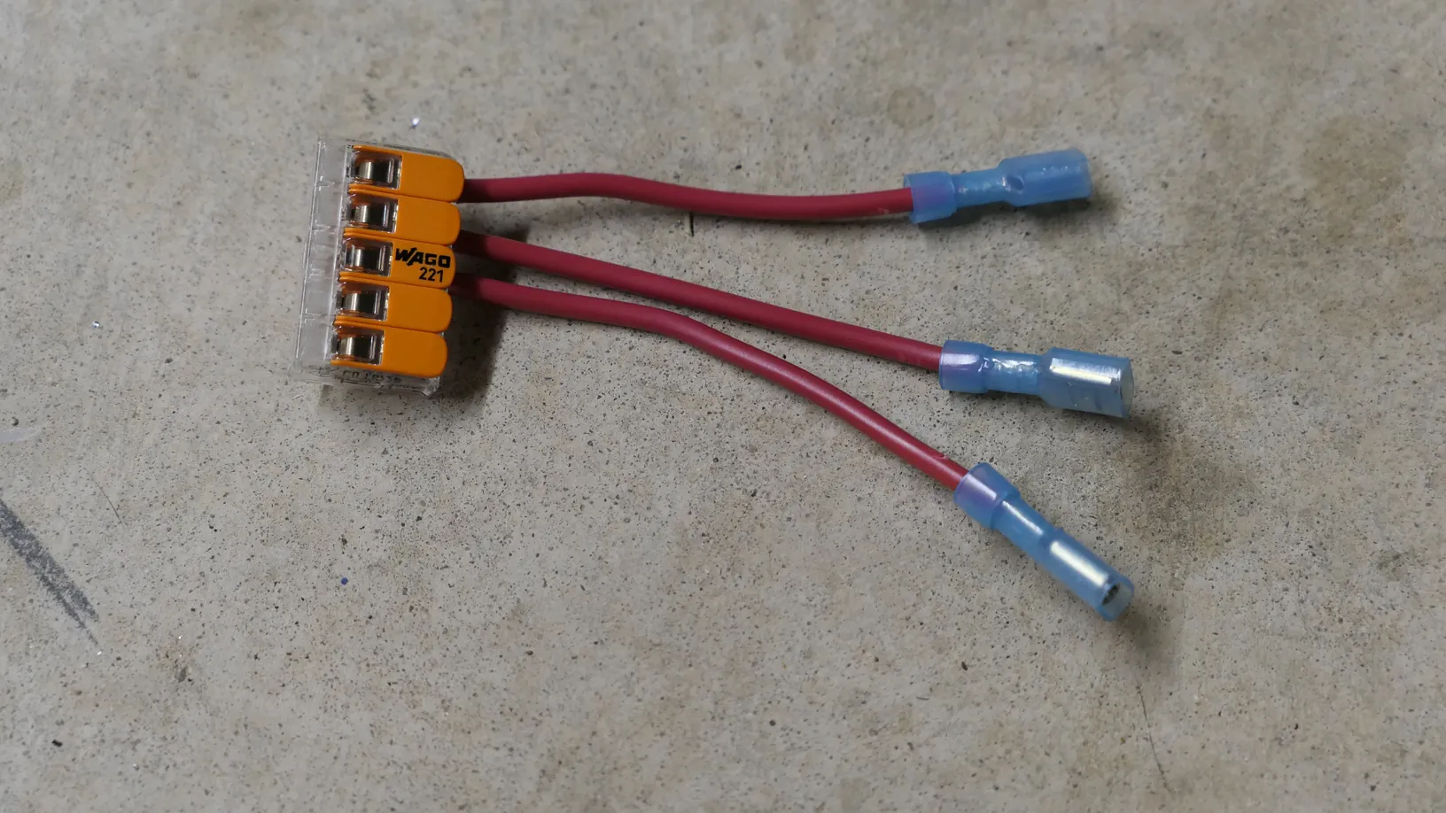
Connect all negatives to the same 5-port wago as used in Step 8 for powering the indicator LEDs.
Step 11: Connect Battery
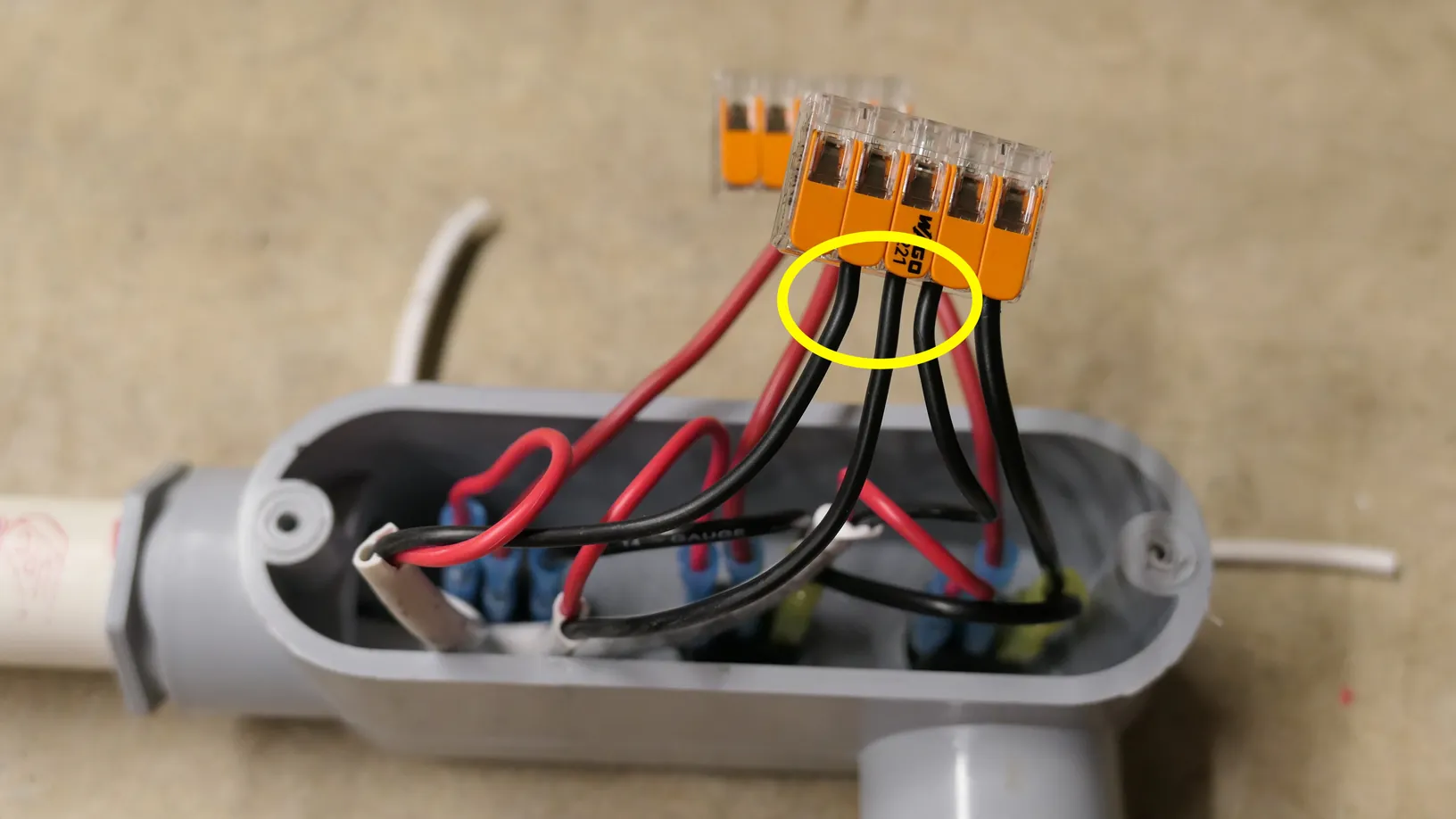
Using 12ga marine wire, run the positive to the positive Wago and negative to the negative Wago.
Using butt connectors, add a 20amp fuse inline with the positive line and a female spade connector. Add a female space connector on the negative line as well.

Use Wago connectors to combine the three ground wires into a single main return line, and combine the switch power leads into a single hot line running back to your battery pack.
Step 12: Hook Up the Battery
Connect the leads to your 12V 18Ah battery (which drops perfectly into my Eberlestock Bandit backpack and flip each toggle to make sure the individual circuits fire up cleanly before you head to the coast.
Materials Needed
(May Contain Links that Earn Commission)
Wrapping Up
This aluminum Redux design completely changes the game on the flats. By swapping the flexible PVC for a rigid aluminum frame, you get a solid, direct feel when scanning the bottom, and the custom wrist cuff distributes the weight so well that you can wade all night without your wrist locking up. The combination of the bored-out 1-inch to 1/2-inch reducer bushing and the custom-fit 1/2-inch PVC cap keeps the entire system completely watertight while retaining that handy 1-inch LL conduit enclosure at the handle.
Hope it helps y'all!