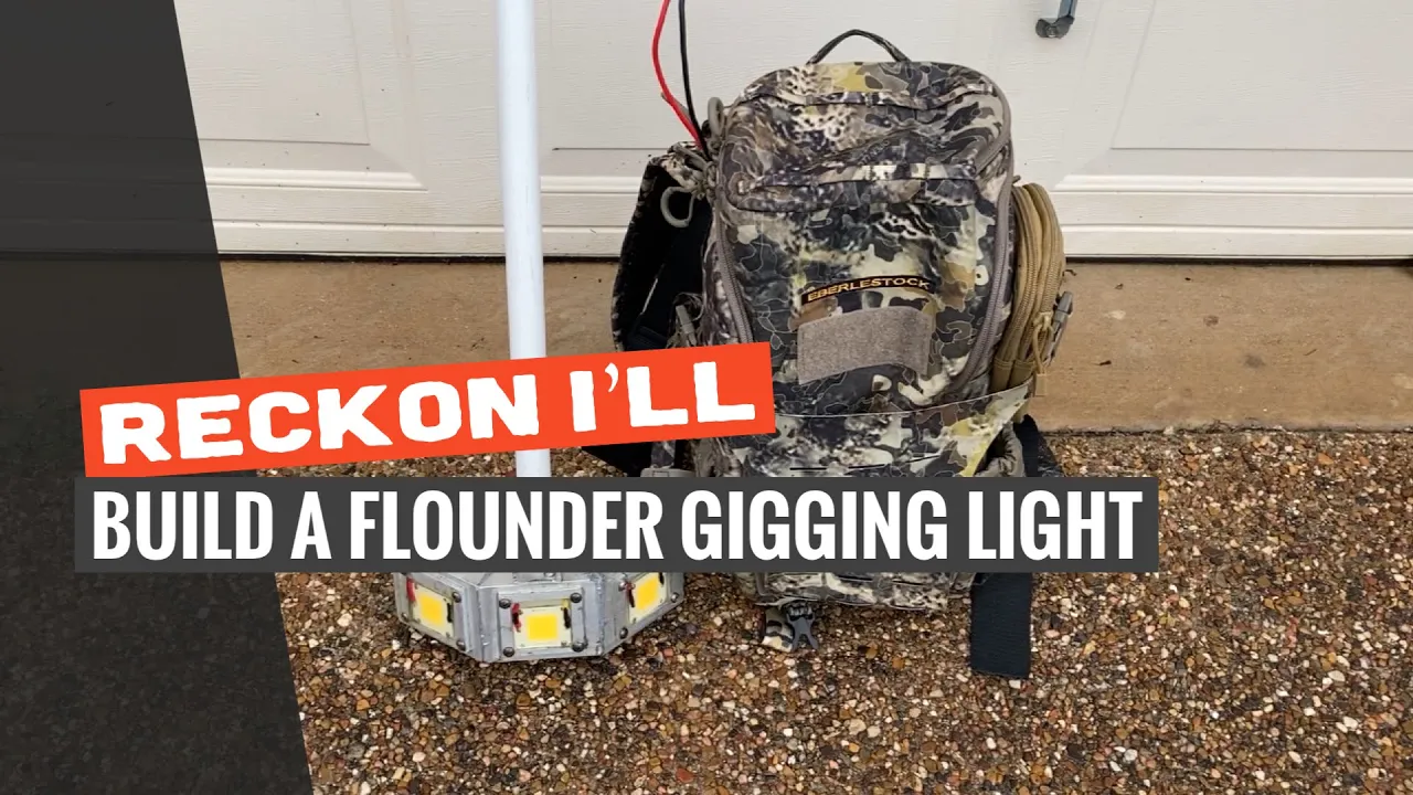
DIY: Build a Gigging Light that Will Give the Flounder a Sunburn
I only recommend products I believe in and use myself. If you purchase something using a link to an item on a post, I may earn a small commission at no additional cost to you. Read More
This is one of the more involved DIY projects I've tackled, but the result is a professional-grade flounder gigging light that rivals high-end custom versions. By using three independent 50W LED chips and a custom aluminum housing, you get maximum illumination with the ability to manage your power consumption on the fly.
Overview: The Goal
The mission was simple: squeeze massive light output out of a handheld pole while keeping the battery setup light enough to carry in a backpack.
Note: These LEDs generate significant heat and should only be run for extended periods while submerged in water to prevent burnout.
Step 1: Miter the Three Base Pieces
Start with three 4” pieces of 3” x 1.5” aluminum rectangle tube. Scribe 22.5° miters for the frame: the center piece gets miters on both sides, while the two outer pieces keep a square outside end.
Step 2: Cut the Top Bracket
Cut a 1.5” section of 1" square tube to serve as the top bracket, then remove the top wall so it becomes a U-shaped bracket that can capture and support the pole connection.
Step 3: Cut Flat Stock for LED Chip Surrounding
Each LED chip needs an aluminum border to hold the waterproofing epoxy. If you have rectangle tube on hand, cut off the sidewall and trim it into lengths of flat stock instead of buying separate material.
Step 4: Cut Out Three LED Surroundings from the Flat Stock
After a few frustrating attempts, the cleanest method was using a 1 7/8” hole saw to open the center, then scribing the circle into a square and finishing the cuts with a jigsaw.
Step 5: Attach the Surroundings to the Housing
Tap holes around each housing section and fasten the LED surrounds with stainless bolts. This keeps the parts aligned and works well if you plan to braze instead of weld.
Step 6: Braze the Housing Together
Braze the three housing sections together if you do not have a spool gun. Multiple joints can be tricky, but MAP gas helps speed up the process and the result is strong enough for this build.
Step 7: Drill A Hole in Middle Housing
Use a 1” hole saw to drill the back of the middle housing. This opening gives you a clean path for routing wire into the center light section.
Step 8: Drill Hole to Attach Pole to the Bracket
Drill a horizontal hole through the bracket with a 5/16” bit. This hole will be used to attach the PVC handle to the metal bracket.
Step 9: Drill Holes to Attach and Wire the Bracket to Lights
Drill and tap two holes through the bracket and into the light body for mounting. Then drill a larger pass-through hole so the wire can reach the center light.
Step 10: Drill Wire Hole for Side Lights
Drill a 3/8” hole in each side housing. These holes give the side light wires a dedicated path out of the housing and toward the pole.
Step 11: Prepare PVC Pole for Hinge
Cut a 72” length of 3/4” PVC and cap it. Center the hinge on the pole, use it as a template for a 5/16” hole, then drill a 3/8” wire pass-through above the cap.
Step 12: Drill Hole in PVC for Wiring
Drill a 1/2” hole in the PVC so the wiring can pass cleanly through the pole and into the light housing without being pinched.
Step 13: Drill Wiring Holes in Housing
Drill two 1/8” holes in the front of each housing section. These small holes let you route wiring directly to each LED chip.
Step 14: Drill Holes to Attach LED Chips
Use an LED chip as a template, then drill and tap 4-40 holes for mounting. Apply thermal paste to the back of each chip before screwing it into place.
Step 15: Install Switches
Drill three 5/8” holes in the junction box and widen them as needed with a multi-tool so the switches press firmly into place.
Step 16: Attach PVC Junction Box
Attach the junction box to the far end of the PVC pipe. A little marine epoxy can help lock everything in place, even if the application gets a bit messy.
Step 17: Wire and Solder Each LED
Run three lengths of 12-2 wire from the junction box to the light housing, leaving enough slack to work. Route side light wires through the side holes and the center wire through the hinge, then solder each to its LED chip.
Step 18: Wire The Accessory-side of each Switch
Connect the hot wire from each light to a spade connector on the accessory side of its switch. Keeping each switch separate makes troubleshooting easier later.
Step 19: Splice Ground Wires
Connect spade terminals to the ground side of each switch, then combine the switch grounds and light grounds with a ground wire running back to the battery. A Wago connector keeps this compact and serviceable.
Step 20: Wire The Hot To each Switch
Run a separate hot-in wire to the middle terminal of each switch. Do not daisy-chain the hot side; combine the leads separately in a Wago port or with solder and heat shrink.
Step 21: Connect to the Battery
Run hot and ground leads out of the junction box long enough to reach a backpack battery. Add a 15 amp fuse to the hot side, crimp spade terminals, and briefly test the lights before waterproofing.
Step 22: Heatshrink Your Connections
Once everything tests correctly, heat shrink any exposed or finished connections that need protection before the epoxy and final assembly steps.
Step 23: Mix and Pour Epoxy Onto One Light at a Time
Because the lights are angled, pour and cure one cavity at a time. Mix epoxy as directed, pour it evenly around the LED, and briefly use a heat gun to pull out air bubbles.
Step 24: Assemble and Attach the Handle
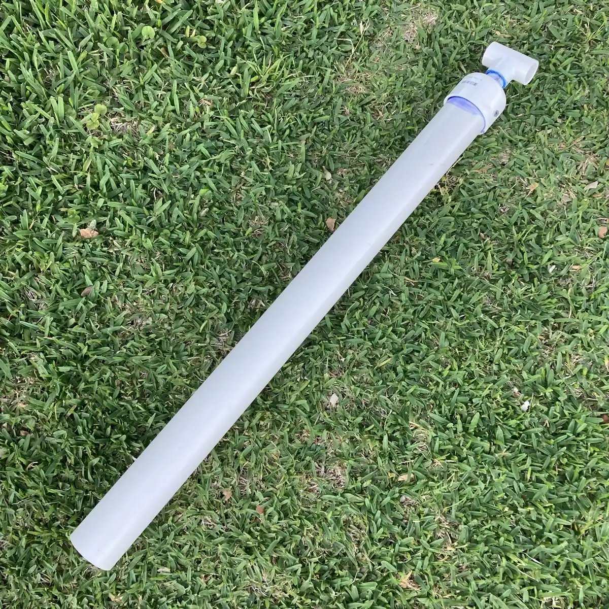
Thread the 3/4” thread/slip joint into the clip-on tee, glue in a comfortable length of 3/4” pipe, and clip the handle wherever it feels best on the pole.
Retrospective: What I Would Change
The concept worked well, but a welder with a spool gun would be faster than brazing. I would also consider lighter wiring, a thicker LED surround, 1” PVC for more room, and thicker plate with rear wiring access.
Materials Needed
(May Contain Links that Earn Commission)
•
3″ x 1.5″ Aluminum Rectangle Tube•
2″ x 1.5″ Aluminum Rectangle Tube•
3/4″ SCH40 PVC•
12ga, 15amp inline fuse•
10-12ga Female Spade Terminals•
3/4″ reducer (to adapt to 3/4″ pipe)•
LL Conduit Enclosure, 1″