DIY: Build a Jig to Tie A Better Double Dropper Rig
I only recommend products I believe in and use myself. If you purchase something using a link to an item on a post, I may earn a small commission at no additional cost to you. Read More
Improving On An Already Good Thing
The concept of a board to tie double-dropper rigs is not novel…I’ve seen several iterations, all with there own flare.
My motivation for my take on the dropper-rig board can be seen in the picture below:

What I Want In a Dropper Rig Board
As you can see, my original board is made of MDF and tacks. It’s given to bending the tacks, snagging your clothing or skin and difficult to store and transport.
My ideal board needs to provide the following:
Ease Of Transport
I need a board that can be easily and compactly stashed in the car for our long road trips to Florida. No bent nails and puncture wounds!
Versatility
Depending on the conditions, I experiment with different leader lengths and loop lengths. I want a board that can vary sizes of leaders produced.
Reinventing the Dropper Loop Board
It wasn’t until I articulated my ideas around this project to my wife that I got the inspiration needed. I was originally planning a concept using rare earth magnets and dowels when I remembered the mind teaser puzzles I played with while waiting for food at the Cracker Barrel.

The final design of this board is based on the game that uses golf tees to change the configuration of the puzzle. It will support dropper loops for the following loop and lead lengths:
Dropper Loop Size | Distance between Mainline, Loops and Sinker |
|---|---|
2" | 10" |
3" | 10" |
4" | 10" |
5" | 12" |
6" | 14" |
Related Posts

DIY: Save Your Fish Bites and Fish Gum from Going Bad and Other Tips for Winterizing Your Surf Gear

DIY: Build A Tackle Storage System On A Surf Fishing Cart

DIY: Build a No-Weld Fishing Sand Spike That Will Stand Up to the Surf

DIY: Make a Surf Fishing Sand Spike That Stands Up to a Tsunami

DIY: Trick Out An Aluminum Pull Cart for Fishing the Surf
Step 1: Scribe A Line Lengthwise
Scribe a line across the bottom of the board (I used the width of a yard stick). This will serve as the first reference point for your measurements.

Step 2: Scribe a Perpendicular Line at the Midpoint
Find the midpoint of your horizontal line and scribe another perpendicular line. This will be your second point of reference.

Step 3: Measure Your First “Triangle”
The pegs of the board will be placed as equilateral triangles. The technique I’m going to demonstrate will prevent you from having to dust off your memory of the Pythagorean Theorem.
Just remember that the length of 1 side of your equilateral triangle will equal the length of your dropper loop. Since we are going to support from 2″ – 6″ dropper loops, you will measure half the distance of your dropper loop.
The picture above is me measuring for the 3″ dropper loop (I decided to add 2″ support later) so that is why the digital calipers read: 1.5″ (half of 3″).

Tip: Use Digital Calipers
You can use a ruler or tape to measure, but the benefit of the digital calipers is precision as well as the ability to use the share end to push into the pine board and make the hole location…its just faster and you are going to be marking a lot of holes!
Step 4: Mark the Remaining Triangle Bases
Using your calipers, continue to mark the remaining measurements for each dropper loop size. Again, the picture above doesn’t show the 2″ loop marks, but the measurements would be the following respectively: 1″, 1.5″, 2″, 2.5″, 3″….if you make the same marks on both sides of the midpoint, you will have loops of 2″, 3″, 4″, 5″, 6″.

Step 5: Mark the Remaining Triangle Bases
The next step is to mark the top of the triangle. Simply set the full length of desired loop and measure from one of the corresponding mark on the baseline to the scribed line.
The picture below shows the completion of the 3″ triangle.

Step 6: Complete Remaining Triangles
Complete Step 5 for each remaining triangle.

Step 7: Measure Distance for Fixed Post Points
From the 6″ marking on the baseline, measure out 1.5″ to mark the location for a post post. Repeat on the left-side of the baseline as well.
This location will be universally as an anchor point for all dropper loop sizes.

Step 8: Measure Termination Point Distance for 2″ Dropper Loop
I’ve already done the math to get the leader lengths described in the introduction. Holding a speed square to the board, measure 4.5″ between the fixed post point you marked in Step 7 flush with the speed square.
This point marks the termination point to always have 10″ of line between each loop, the sinker, or the end attached to your main line.
This is known, because the right-leader length is the distance from the left baseline point of the triangle and the termination point you just calculated. If you measure yourself, you will find 5.5in from the left-side to the fixed post point… you then need a point that is 4.5″ away to makeup the 10″.

Step 9: Measure the 3″ and 4″ and 5″ termination points
The 3″ and 4″ points can be measured by measuring .5″ back towards the baseline from the 2″ point you marked in Step 8.
The 5″ point, since the leader for the 5″ loop will be 12″, can be measured .5″ from the 2″ mark in Step 7, going away from the baseline.

Again, this can be easily confirmed by measuring from the left-side of the triangle in question to the termination point.
Once complete you will have a straight line of termination points.

Step 10: Mark the 6″ Loop Termination Point
Since the 6″ loop will have a 14″ leader, measure 1.5″ from the 5″ termination point you marked in Step 9.

Step 11: Set Angle for Left-side Termination Points
Rather than use a 45 degree angle, offset the speed square on the left-side to give yourself more room to place the spool of line. The marks in the picture above were my original marks, but I opted to offest a bit and scribe a line.

Step 11: Set Angle for Left-side Termination Points
Repeat the process from Steps 8 – 10 for the left-side of the board.

Step 12: Set Angle for Left-side Termination Points
Using a 11/64″ drill bit, drill out each hole on the board marked.

Step 13: Drill a Hole for the Spool
Location doesn’t have to be precise, but drill a hole toward the top left of the board to hole the spool of line.

Step 14: Round Off the Board Edges
Smooth the edges using a 1/4″ roundover bit.

Step 15: Bisect End of Board
Find the center of the board edge and make a mark. This will be used to build a place to store the parts of the board when not in use.

Step 16: Measure Holes on Both Sides of Midpoint Mark
Measure 8 marks (9 if you drill the center mark).

Step 17: Drill Out Holes
Drill a small pilot hole for each mark and slowly step up to a 3/16″ bit being careful drill straight down (we want the extra room on these holes so the larger bit is needed).

Tip: Use A Standup Drill Press
Ideally, you would do this drilling with a standup drill press, but I unfortunately don’t have one with enough clearance so hand-drilled.
Step 18: Burn Key onto Back of Board
With all those holes, I figured a key was in order. I came up with a unique mark for each combination and burned it into the back for reference.

Tip: Write In Pencil First
I found it easier to write in pencil what I plan to burn into the wood and then trace it with the wood burner.
Step 19: Transfer Key Symbols to the Board
Use the symbols in the key to mark the holes to use with the preferred dropper loop size.

Step 20: Add a Finish
Stain (I used Golden Oak) and seal with 3 coats of polyurethane.

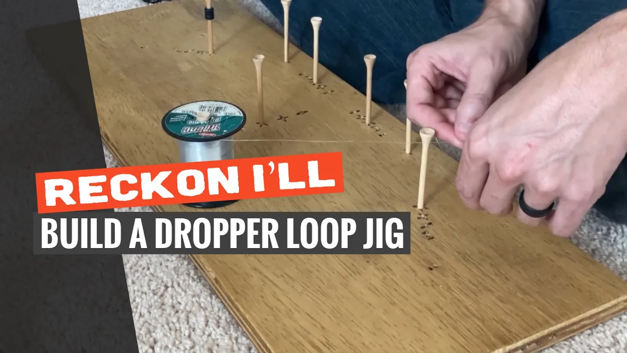
The Finished Product


How To Use It
Step 1: Install the Spool
Anchor the Spool with A Tee

Step 2: Install the Line Holder

Step 3: Install the Fixed Posts

Step 4: Setup Triangle for the Desired Size

Step 5: Tie a Figure Eight Knot (Used for Sinker Attachment)

Step 6: Wrap Around the Jig

Step 7: Anchor at Knot
Wedge the figure-8 knot between the gaskets

Step 8: Twist Base of Triangle Six Times

Step 9: Remove Line From Top of Triangle and Push Through Center of Twist

Step 9: Return Line to Post and Tighten By Pulling Out

Step 10: Re-thread Jig and Anchore at Loop from Step 9
Step 11: Tie Another Loop Using Steps 7 – 9
Step 12: Cut Line at Left-side Termination Point

Step 13: Tie A Perfection Loop for Attaching to Main Line

Materials Needed
(May Contain Links that Earn Commission)
•
3/4” Plywood 28″ x 10″Tools Needed
(May Contain Links that Earn Commission)